
Helicoil Type Threaded Inserts-Technical Studies & Data on Pullout Strength and Fastener Breakage by The University of Bristol
Although the paper reproduced below is dated 1954, it’s findings are still as current as back then and are reassuring to anybody who has any doubt about strength issues and wire type screw thread inserts [STI’s]. We are not aware of a lot of other formal work publicly available on the strength of these inserts although Helicoil themselves have published data from time to time related to various specific requirements.
Our frank advice based on experience of about 40 years is that there is not a stronger thread at original size than a wire thread insert of correct length and fitted properly. However, there are some uses for thin walled thread inserts where we would not recommend helicoil type inserts but Time-Serts. If a thread is “static” i.e. not likely to be done up and undone more than a few times in its lifetime, we would always say a helicoil type thread is the strongest option. However, for threads that are used over and over again like sparkplug or sump plug threads a helicoil type insert tends to work its way out of the parent hole over time and a Time-Sert is the more permanent repair. There is not a lot of difference in strength between a Time-Sert and a wire STI and both protect soft alloys from stripping. Wire STI’s do have the advantage of acting like a “shock absorber” between parent and fastener and because of this increase the fatigue life of assemblies. The other place where a solid bush such as a Time-Sert has an advantage is in threads that are difficult to access such as down a deep hole. Time-Serts are also generally easier to fit because they are solid and in particular in fine threads they help prevent mis-fitting that can occur with wire wound STI’s.
There is a common strength-related pitfall we’ll mention here but it applies to any type of thread insert and not just the helicoil types. And it is mainly in thread repair not in original equipment use where helicoil type thread inserts often get the blame for a problem when they don’t deserve it. Light alloys seem to fatigue over time and particularly where they are constantly heated and cooled. These alloys then become less able to hold a thread without stripping. This occurs commonly in alloy engine blocks. Then when a stripped thread is repaired by an inexperienced repairer who uses a standard length helicoil type insert the insert immediately strips again. The problem here is that a longer insert should have been used or alternatively a thicker walled insert (and probably longer) would have solved the problem. However, very occasionally alloys seem to age so badly that no amount of tender care will stop a thread from stripping.
Thread Inserts
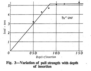
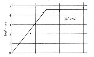
By B. CROSSLAND, M.Sc.,Ph.D, A. MIMech E., A.F.R.A.S. Some pull tests on thread inserts in two light alloys, carried out at the University of Bristol are here recorded. Incidentally the tests revealed that the conventional depth of insertion of mild steel studs is necessarily large.
HIGH-TENSILE steel thread inserts into light alloy were first produced commercially under the name of ” Aero Threads,”though the idea of thread inserts as such dates back much further Theseinserts were helically wound from high-tensile steel or bronze spring wire and fitted in holes previciously drilled and tapped in the light alloy.The thread in the light alloy was a normal vee thread, and the wire insert was formed so that it had the correct profile to fit this thread. The profile of the part of the wire insert which mated with the stud was semi circular and this fitted a thread of similar profile cut on the stud. This form of thread insert is shown in Fig. 1.The advantages claimed for the Aero Thread are, first, that the fatigue resistance of the stud is improved, as there is no appreciable notch effect such as that given by a normal vee thread. Secondly, the stud or

set screw can be removed without damaging the light alloy, as the thread insert fully pro test the soft threads in the tapped hole in the light alloy. A disadvantage of this form of insert is in the maintenance of sufficiently good tolerances in the manufacture of the stud and insert Within the past few years high-tensile steel wire inserts have been produced by the Cross Manufacturing Company, Ltd., of Bath. These inserts are designed to fit a stud having a normal thread profile as shown in Fig. 2. Very good accuracy in profile and
dimensions is obtained by a hot rolling process, and these inserts have been approved by the O.L.D. The range of inserts so far produced is from 4 B.A. up to 7 in diameter, though there is no difficulty in producing even larger sizes; they are available for nearly all the threads commonly used in this country. A few samples of these inserts were sub mitted to the University of Bristol by the Cross Manufacturing Company, Ltd., for test, and the results appeared to be of sufi-cant interest to warrant furt her tests, particularly in view of the small amount of information available on this topic. The practical engineer has adopted various empirical figures for the depth of insertion of mild steel studs into various metals, such as
2D for aluminium, TD for cast iron, bronze and brass, and ID for steel, though these figures have little or no experimental backing, For high-tensile studs there seems to be no generally accepted figure, though the British: Standard 171 recommends that the depth of insertion into aluminium should be 2D
tests were also carried out on the two light alloys used, to find the tensile and shear properties. With the tension tests axial loading shackles were used, and special torsion grips were employed to ensure that only a pure couple was applied to the torsion specimens. From the torsion test it washoped that the shear stress at failure could be deduced.For these tests the studs were made from a high-tensile steel having an ultimate strength of 68 tons per square inch; the two light alloys were an aluminium to specification
B.S.6.LI and a zirconium magnesium such as that used in the aircraft industry. The zirconium magnesium was supplied by the Bristol Aeroplane Company and was to its specification BACE 239. Most of the tests were with studs having gin UNF and UNC threads, though a few tests were also carried out on lin and in UNF and UNC threads.

RESULTS AND DISCUSSION
Tension Tests.-Two specimens of eachmaterial were tested with the results given below -Aluminium ultimate strength 31.6 tons and 32.5 tons per square inch, giving an average of 32 1 tons per square inch.Zirconium magnesium : ultimate strength 7.70 tons and 7.82 tons per square inch, giving an average of 7 76 tons per square inch.The aluminium specimens gave a normal ductile fracture with an ap preciable reduc-tion of area, whereas the zirconium mag-nesium gave a typical brittle fracture with asmaller reduction of area.. Torsion Test.-Three specimens of each material were tested to failure, the torque and the strain in the gauge length being measured throughout the test. The torque strain curves were drawn and the shear stress was deduced by the method suggested by Nadai (Theory of Flow and Fracture of Solids, Vol. I, published by McGraw-Hill), so that the shear stress at failure could be determinedThis gave an ultimate shear stress for aluminium of 172 tons per square inch and nda shear stress at failure for the zin conium magnesium of 6.3 tons per square inch.
The aluminium specimens failed in a planetransverse to the axis of the specimen (i.e. typical shear fracture), but the zirconiummagnesium failed on a helical plane inclined at 45 deg. to the axis of the specimen,which shows that the specimen had failed due to the tensile component of the shear stress. Consequently the shear stress at failure for the zirconium magnesium torsion specimen is not necessarily the ultimate shear stress for the material, and it may well be that the ultimate is much higher than the figure of 6.3 tons per square inch.Compression Tests on Zirconium Mag-nesium. It was considered that the ultimate shear stress could be found from a com-pression test, as failure of a brittle material in compression mostly occurs along the planeof maximum shear. Two compressionspecimens were tested between hardened steel plates, the ends of the specimens being lubricated throughout the test with calciumoleate to prevent “barrelling.” Both tests gave identical results and failure in both cases was approximately at 45 deg. to the axis of thespecimen (i.e. plane of maximum shear). The derived value of the ultimate shear stress on the plane of failure was 7-65 tons per square inch (i.e. half the compressive stress at the instant failure took place).

stress based on the diameter of the threadin the light alloy has been calculated and this figure is given in Table L This assumes that shearing takes place on an area equal to the product of the diameter of the thread in the light alloy and the depth of insertion..
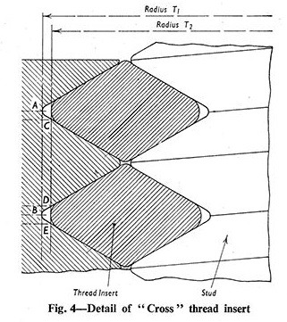
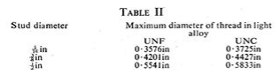
The diameters of the threads in the lightalloy to take the thread inserts are given in Table II.The last column in Table I gives the ratioof the nominal shear stress at failure of the insert to the ultimate shear stress determined from either a torsion or compression test; this might be regarded asthe “shear effi-ciency of a thread.” It will be seen that this ratio is reasonably constant within the limits of experimental and manufacturing errors.
The last column in Table I gives the ratio of the nominal shear stress at failure of the insert to the ultimate shear stress determinedfrom either a torsion or compression test; this might be regarded as the “shear effi-ciency of a thread.” It will be seen that this ratio is reasonably constant within the limits of experimental and manufacturing errors. That the ratio is not unity is due to the tip arance bed in the clearance between the thread insert and the thread tapped in the light alloy, which reduces the effective area over which shear occurs. This is made clear in Fig. 4; the nominal shear stress given in Table I is worked out on an area equal to 2nr, x depth of insertion, whereas shear actually occurs over an area of 2nr,x C CEX depth of of insertion. From examination of the sheared threads the value of CD/CE is approximately 2, this would give a value of rrx CODE less than 0-75, which is in fair agreement with the experimental value given in the last column of Table I. Two cases of a tension failure of the zirconium magnesium were noted. With this type of failure a shallow conical-shaped piece of the material was pulled out of the test block. This form of failure only occurs for small depths of insertion in brittle materials. In the two tensile failures expiry- ences the shear ratio at the maximum load indicates that a shear failure might have equally well occurred. It has been seen that the strength of the thread in the light alloy is closely related to the ultimate shear strength of the alloy, asmight be expected. From examination of the values of the ultimate shear stress and the ultimate tensile strength it can be seen that the strength of the threads in the light alloy is not related to the tensile strength.
Index - Click to go to required page
University of Bristol Study on Pullout Strength
Metric (ISO) Tapped Hole Sizes Table
UNC Tapped Hole Sizes Table
UNF Tapped Hole Sizes Table
BSW/BSF Tapped Hole Sizes Table
BSPP/BSPF Tapped Hole Sizes Table
BA Tapped Hole Sizes Table
NPT Tapped Hole Sizes Data
Sparkplug Tapped Hole Sizes Table
ADDRESS:-PO Box 55, KOTARA NSW 2289 AUSTRALIA
PHONE:- (in Australia) 1 800 025 500 or 02 4920 8966 (International)+61 249 208 966
EMAIL:-
sales@crosstools.com.au
8am – 5pm
Monday to Friday
Eastern Standard or Summer Time
[DISPLAY_ULTIMATE_SOCIAL_ICONS]